

Insights

Industries Utilizing the Pneumatic Tube Systems

Hospitals / Pharmacy

Banking / Financial

Automotive
Warehouse / Industrial

Offices / Retail
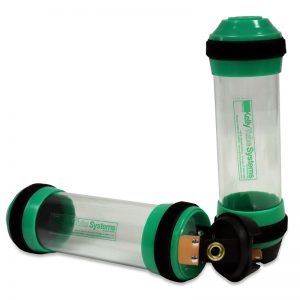
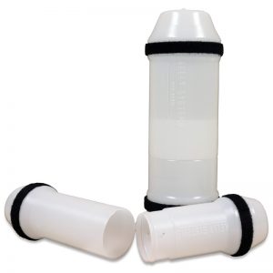
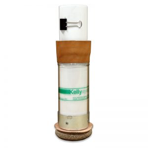
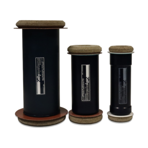
SAMPLE TRANSPORT
FOOD PROCESSING PLANTS • PAINT AND CHEMICAL PROCESSING PLANTS • OIL REFINERIES • METALS PRODUCING: STEEL AND ALUMINUM MILLS • PHARMACEUTICAL PLANTS • LIVE STOCK BREEDING FACILITIES • HOSPITALS
INDUSTRIAL SAMPLE TRANSPORT VIDEO
STEEL MILL SAMPLE TRANSPORT FLYER (PDF)
Sample Transport Brochure (PDF)
Published Case Study on Sample Transport (PDF)
PRODUCT MOVEMENT
AUTOMOBILE ASSEMBLY PLANTS • MANUFACTURING SHOPS
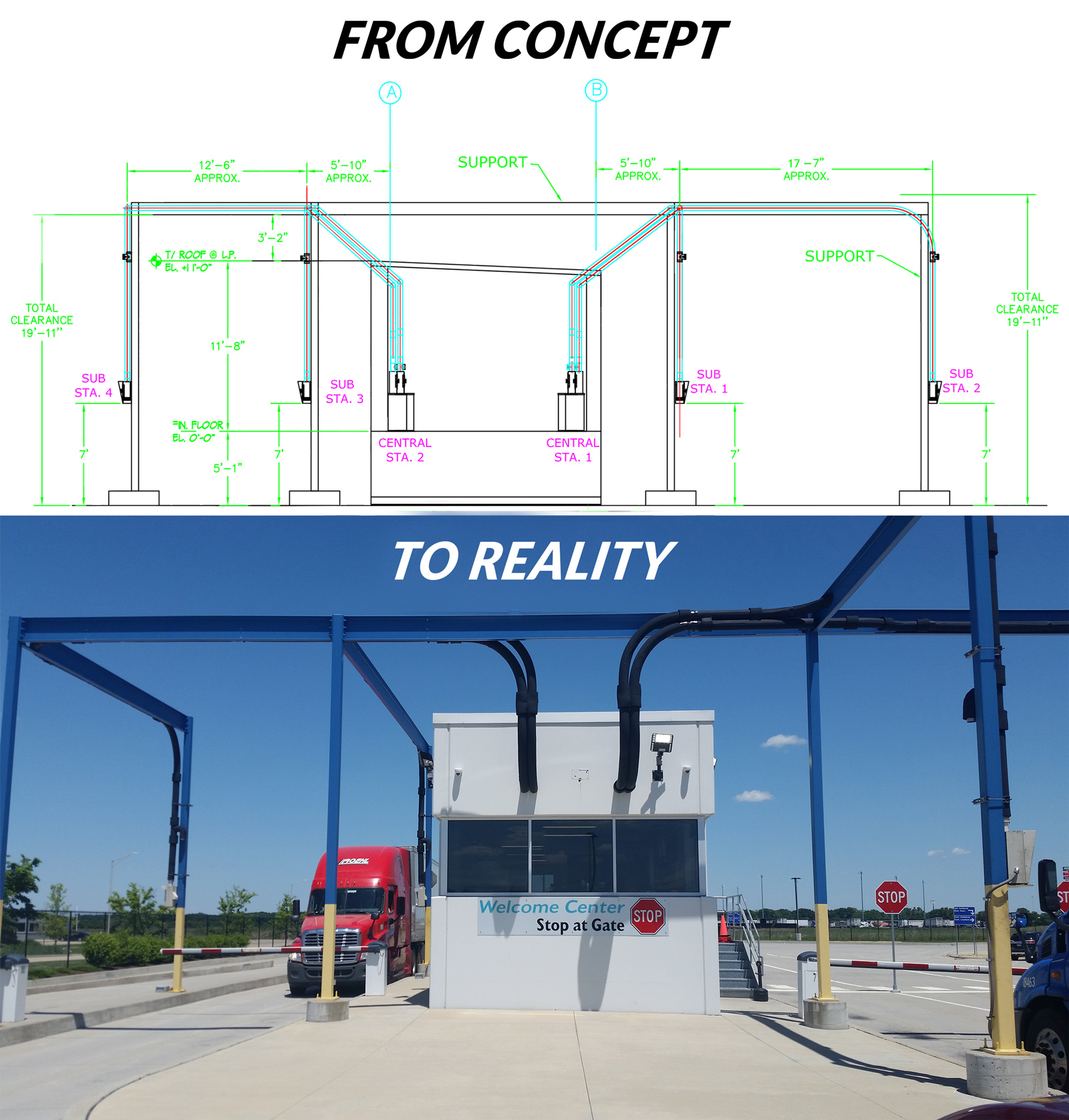
CASH AND DOCUMENT TRANSPORT
RETAIL STORES • CAR DEALERSHIPS/ OFFICES • CANNABIS DISPENSERIES • BIG BOX WAREHOUSE STORES • CASINO GAMING • BANK DRIVE-UP • PHARMACY DRIVE-UP • FREIGHT TERMINALS • TRUCK SCALE • DISTRIBUTION CENTERS.
Kelly Systems Inc.
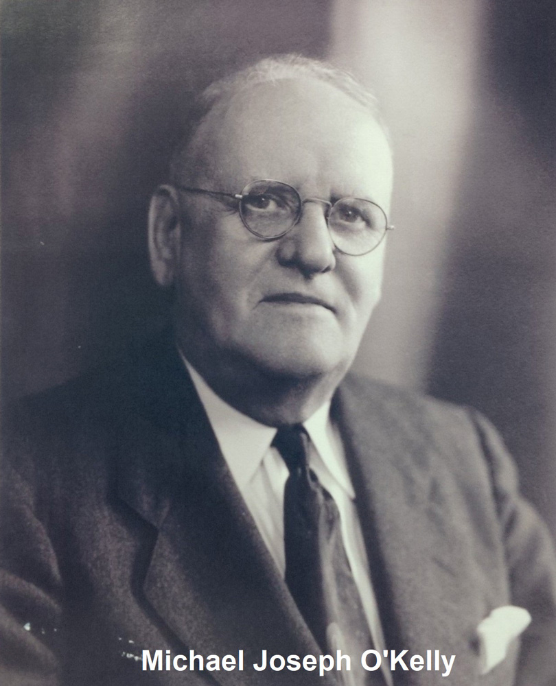 Kelly Systems Inc. founded in 1904 by Michael Joseph O'Kelly is a 4th generation Family owned American business. Mr. O’Kelly saw the opportunities in physical material transport by means of the Pneumatic Tube System (PTS) and created Kelly Systems Inc. to supply the Chicago industries eventually leading to the fastest growing businesses of that time such as SEARS.
Current customers range from; (Restaurants, Food Processing, Automotive, Retail, Hospitals, to name only a few.) The Kelly Tube Systems which help run those companies operations are highly depended upon to deliver reliable and safe operations.
Customers We Serve Who Serve You


Contact Us
To obtain additional information regarding the Kelly Tube solution best suited for your application…to request a “ball-park” cost estimate for your budget planning…to request a bid for an active project specifying a pneumatic tube system… to request a meeting at your site for preparation of a proposal for a complete Kelly Tube System to meet your needs…or to request assistance with your existing pneumatic tube system, please give us a call or fill out the form below.